


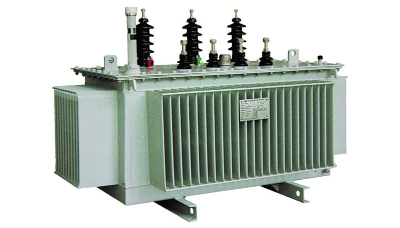
S(B)H15 series oil-immersed amorphous alloy core transformer
Amorphous alloys use an advanced ultra-quenching technology to spray liquid melts such as iron, cobalt, boron, and silicon onto a very high-speed chassis and rapidly cool them to form a thin strip of 0.02 mm to 0.04 mm. It has excellent soft magnetic properties, corrosion resistance and high electrical resistivity.
Amorphous alloy materials have the following advantages compared with cold-rolled grain-oriented silicon steel sheets:
1. Amorphous alloy is a new type of material. It has no crystal structure and is an isotropic soft magnetic material with low magnetization power.
2. There is no structural defect that hinders the movement of the magnetic domain wall, and the hysteresis loss is smaller than that of the silicon steel sheet.
3. The resistivity is extremely high, which is 3~6 times of silicon steel sheet. The eddy current loss is greatly reduced, and the unit eddy current loss is only 20%~30% of silicon steel sheet.
Product use and characteristics
A. Product use
S(B)H15-M oil-immersed amorphous alloy core transformer has low no-load loss; the fuel tank is designed as a fully sealed structure, and the oil in the transformer is not in contact with the outside air, preventing oxidation of the oil and prolonging the service life of the product. At the same time, it saves maintenance costs for users. Applicable to all power distribution sites, urban and rural residential electricity, especially in places where power is scarce.
B. S (B) H15-M oil-immersed amorphous alloy core transformer features:
1. Low energy consumption: It adopts isotropic soft magnetic magnetic conductive material with low magnetization power, high resistivity and low eddy current loss. The core made of amorphous alloy material has a low no-load loss and no-load current, which is only 1/3 of the silicon steel sheet. The no-load loss of the transformer is about 75% lower than the S9 series specified value, about 65% lower than the S11 series, and about 50% lower than the S13 series. The operating cost can be greatly reduced, and the energy saving effect is remarkable.
2. Strong anti-short circuit capability: On the structure of the body, the high and low voltage windings are wound on the hard cylinder. When assembling, the windings are supported on a separate winding support system and pressed tightly, so that the core can be not stressed and reduced. When the transformer is short-circuited, it is radially retracted or expanded, thus effectively ensuring the short-circuit resistance of the transformer. In addition to the small capacity of the low-voltage winding, the copper wire is generally used, and the high-voltage winding adopts a multi-layer cylindrical structure to balance the ampule distribution of the winding and the leakage magnetic flux is small. The high and low voltage coils are wound together using a wire tensioning device, shaping and press-fitting processes to enhance the strength and resistance to short circuits. The product adopts three-phase five-column structure, surrounded by frame structure protection, and the structure is compact and reasonable. This structure has passed the test of multiple short-circuit bearing capacity.
3. Low noise: select reasonable working magnetic density during product design, improve core and coil structure during product processing, use special noise reduction materials and other processes and measures to make the product noise far lower than the international JB/T10088 requirements.
4. Strong anti-corrosion ability: The amorphous alloy core is fully encapsulated to effectively prevent rust and amorphous alloy fragments from falling off, thus effectively protecting the core and the coil. The fuel tank and the cover are fully sealed to extend service life and maintenance-free.
5. Reasonable design: The product adopts non-suspension structure, adopts vacuum drying, vacuum oil filtering and oil filling process, and adopts corrugated fuel tank structure.
6. Excellent environmental performance: The use of amorphous alloy iron core transformer can save the amount of natural coal, save water consumption, reduce dust emissions, reduce CO2 emissions, and reduce SO2 emissions.
A. Model Description

Economic and social benefit analysis
Refer to GB/T 6451-2008 oil-immersed power transformer technical parameters and requirements and GB/T 25446-2010 oil-immersed amorphous alloy core distribution transformer technical parameters and requirements, S9-315/10 transformer and SBH15-M-315 The /10 transformer is compared as follows:
S9-315/10 transformer P0=670W, PK=3830W; S(B)H15-M-315/10 transformer P0=170W, Pk=3650W
Energy-saving benefits are calculated according to the formula D=C×H×V
Where C - electricity price, 0.86 yuan / kWh;
H——year running time, take 8760h;
V——loss reduction value in kW;
Calculated according to the above formula:

Therefore, compared with the traditional S9-315/10 transformer, the amorphous alloy oil-immersed transformer SBH15-M-315/10 can run for one year, saving 5957 degrees of electricity and saving electricity by 5,123 yuan.
In summary, if you consider the normal life of the transformer for 30 years, you can save 178,710 kWh, which can save 153,690 yuan in electricity costs, and its economic benefits are extremely impressive.
If considered according to the normal life of the transformer for 30 years, it can save 71.5 tons of natural coal, save 71.5 (ten liters) of clean water, 48 (tons) of dust emission, less CO2178 (tons), and less emissions of SO25.4 (tonnes). ), it can be seen that its social and environmental performance is also very impressive.
Dimensions of the dimensions:

Technical Parameters
型号 | 电压组合 | UX % | PO (W) | PK (W) | IO % | 尺寸(mm) | 重量(kg) | |||||||
高压/低压 (KV) | 高压分接 范围% | L | W | H | d1 | d2 | 心体 | 油重 | 总重 | |||||
SH15-M-30/10 | 10/0.4 | ±2×2.5 | 4 | 33 | 600 | 1.5 | 900 | 600 | 680 | 400 | 550 | 200 | 80 | 420 |
SH15-M-50/10 | 43 | 870 | 1.2 | 950 | 620 | 780 | 400 | 550 | 260 | 110 | 550 | |||
SH15-M-63/10 | 50 | 1040 | 1.1 | 1000 | 680 | 850 | 400 | 550 | 300 | 140 | 620 | |||
SH15-M-80/10 | 60 | 1250 | 1.0 | 1020 | 780 | 950 | 400 | 550 | 380 | 160 | 700 | |||
SH15-M-100/10 | 75 | 1500 | 0.9 | 1060 | 870 | 1030 | 400 | 660 | 420 | 189 | 770 | |||
SH15-M-125/10 | 85 | 1800 | 0.8 | 1100 | 870 | 1100 | 400 | 660 | 500 | 207 | 870 | |||
SH15-M-160/10 | 100 | 2200 | 0.6 | 1180 | 890 | 1150 | 400 | 820 | 590 | 261 | 1030 | |||
S(B)H15-M-200/10 | 120 | 2600 | 0.6 | 1280 | 900 | 1220 | 550 | 820 | 720 | 324 | 1260 | |||
S(B)H15-M-250/10 | 140 | 3050 | 0.6 | 1340 | 950 | 1250 | 550 | 820 | 860 | 342 | 1470 | |||
S(B)H15-M-315/10 | 170 | 3650 | 0.5 | 1390 | 960 | 1300 | 550 | 820 | 980 | 387 | 1670 | |||
S(B)H15-M-400/10 | 200 | 4300 | 0.5 | 1320 | 1100 | 1330 | 660 | 820 | 1260 | 432 | 2020 | |||
S(B)H15-M-500/10 | 240 | 5150 | 0.5 | 1550 | 1100 | 1350 | 660 | 1070 | 1530 | 522 | 2450 | |||
S(B)H15-M-630/10 | 4.5 | 320 | 6200 | 0.3 | 1520 | 1140 | 1400 | 820 | 1070 | 1730 | 567 | 2770 | ||
S(B)H15-M-800/10 | 380 | 7500 | 0.3 | 1550 | 1170 | 1430 | 820 | 1070 | 2050 | 603 | 3130 | |||
S(B)H15-M-1000/10 | 450 | 10300 | 0.3 | 1680 | 1220 | 1450 | 820 | 1070 | 2320 | 711 | 3670 | |||
S(B)H15-M-1250/10 | 530 | 12000 | 0.2 | 1650 | 1440 | 1450 | 820 | 1070 | 2760 | 792 | 4300 | |||
S(B)H15-M-1600/10 | 630 | 14500 | 0.2 | 1740 | 1440 | 1500 | 1070 | 1070 | 3230 | 882 | 4920 | |||
S(B)H15-M-2000/10 | 5 | 750 | 18300 | 0.2 | 1800 | 1500 | 1550 | 1070 | 1070 | 4000 | 960 | 5800 | ||
S(B)H15-M-2500/10 | 900 | 21200 | 0.2 | 1850 | 1500 | 1600 | 1070 | 1070 | 4800 | 1040 | 6500 | |||
Terminals
型号 | 低压接线端子(mm) | 低压0相接线端子(mm) | ||||||||
图形 | b | b1 | d | Б | 图形 | b | b1 | d | Б | |
SH15-M-30/10 | 1 | 35 | 26 | 12.5 | 8 | 1 | 35 | 26 | 12.5 | 8 |
SH15-M-50/10 | 1 | 35 | 26 | 12.5 | 8 | 1 | 35 | 26 | 12.5 | 8 |
SH15-M-80/10 | 1 | 35 | 26 | 12.5 | 8 | 1 | 35 | 26 | 12.5 | 8 |
SH15-M-100/10 | 1 | 35 | 26 | 12.5 | 8 | 1 | 35 | 26 | 12.5 | 8 |
SH15-M-160/10 | 1 | 35 | 26 | 12.5 | 8 | 1 | 35 | 26 | 12.5 | 8 |
S(B)H15-M-200/10 | 2 | 35 | 26 | 12.5 | 8 | 2 | 35 | 26 | 12.5 | 8 |
S(B)H15-M-250/10 | 2 | 46 | 26 | 12.5 | 10 | 2 | 56 | 26 | 12.5 | 10 |
S(B)H15-M-315/10 | 2 | 46 | 26 | 12.5 | 10 | |||||
S(B)H15-M-500/10 | 3 | 80 | 45 | 14.5 | 13 | 3 | 80 | 45 | 14.5 | 13 |
S(B)H15-M-630/10 | 3 | 80 | 45 | 14.5 | 13 | 3 | 80 | 45 | 14.5 | 13 |
S(B)H15-M-800/10 | 3 | 80 | 45 | 14.5 | 13 | 3 | 80 | 45 | 14.5 | 13 |
S(B)H15-M-1000/10 | 3 | 90 | 45 | 18 | 17 | 3 | 80 | 45 | 14.5 | 13 |
S(B)H15-M-1250/10 | 3 | 100 | 45 | 18 | 17 | 3 | 80 | 45 | 14.5 | 13 |
S(B)H15-M-1600/10 | 3 | 100 | 45 | 18 | 17 | 3 | 100 | 45 | 18 | 17 |
S(B)H15-M-2000/10 | 3 | 100 | 50 | 18 | 20 | 3 | 100 | 50 | 18 | 20 |
S(B)H15-M-2500/10 | 3 | 100 | 50 | 18 | 20 | 3 | 100 | 50 | 18 | 20 |
Note: The external dimensions listed in the above table are for design selection only. The final dimensions are based on the product outline drawing. Due to technical improvements, the above parameters are subject to change without prior notice. Please understand.