
Guideline
The grounding transformer, referred to as the grounding transformer for short, can be divided into oil-type and dry-type according to the filling medium; and can be divided into three-phase grounding transformers and single-phase grounding transformers according to the number of phases. The function of the grounding transformer is to provide an artificial neutral point for systems where the neutral point is not grounded, facilitating the use of arc suppression coils or low-resistance grounding methods to reduce the magnitude of the capacitive current to ground during grounding short-circuit faults in the distribution network, thereby improving the power supply reliability of the distribution system.
In the 6kV, 10kV, and 35kV power grids within the electric power system, the operation mode of neutral point non-grounding is generally adopted. The low-voltage side of the main transformer in the grid is typically connected in a delta configuration, with no neutral point that can be grounded. When a single-phase grounding fault occurs in a neutral point non-grounding system, the line voltage delta remains symmetrical, allowing the electric power system to continue supplying power to users for 1 to 2 hours. Additionally, the capacitive current is relatively small (less than 10A), which does not cause intermittent arcing. Some transient grounding faults can disappear spontaneously, which is very effective in improving power supply reliability and reducing power outage accidents. However, with the continuous expansion of urban power grids and the increasing number of cable outgoing lines, the system's capacitive current to ground has increased sharply, and the capacitive current flowing through the fault point after a single-phase grounding is relatively large (exceeding 10A).
Electric arcs are difficult to extinguish, prone to trigger ferroresonance overvoltage, and generate intermittent arc grounding overvoltage, which may lead to insulation damage, circuit tripping, and escalation of the accident,
Specifically:
The intermittent extinction and reignition of single-phase grounding arcs can generate arc grounding overvoltages, with amplitudes reaching up to 4U (U is the peak value of normal phase voltage) or even higher, and lasting for a long time. This can cause significant damage to the insulation of electrical equipment, leading to breakdowns at weak insulation points and resulting in substantial losses.
Due to the dissociation of air caused by continuous arcing, the insulation of the surrounding air is damaged, making it prone to interphase short circuits.
The generation of ferromagnetic resonance overvoltage can easily burn out voltage transformers and cause damage to lightning arresters, which may even lead to explosions. These consequences will seriously threaten the insulation of power grid equipment and endanger the safe operation of the power grid.
To reduce the capacitive current to ground during a single-phase grounding fault, it is necessary to install compensation devices such as arc suppression coils at the neutral point of the transformer. Therefore, a neutral point needs to be artificially established to facilitate the connection of the arc suppression coil at the neutral point, reduce the grounding short-circuit breaking current, and improve the reliability of system power supply.
■ Current usage status at home and abroad
The grounding transformers commonly used in China adopt Z-type wiring (also known as zigzag wiring). To save investment and substation space, a third winding is often added to the grounding transformer to replace the auxiliary transformer and supply power to the substation equipment. According to China's national standard for "Reactors", the grounding methods for grounding transformers can be divided into direct grounding and grounding through reactors, resistors, and arc suppression coils. Direct grounding has not yet been used in China, but some power research institutions have begun to explore this approach. Grounding transformers abroad typically adopt Z-type connections for 10kV non-grounded systems, forming the grounding protection of the distribution network. When a grounding fault occurs in the system, the grounding transformer exhibits high impedance to positive-sequence and negative-sequence currents and low impedance to zero-sequence currents, ensuring reliable grounding protection.
■ Three-phase grounding transformer
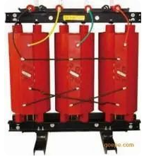
Three-phase grounding transformers use Z-type wiring (also known as meander wiring). The difference between these transformers and ordinary ones is that the coils of each phase are divided into two groups and wound in opposite directions on the magnetic column of that phase. The advantage of this connection is that the zero-sequence magnetic flux can circulate along the magnetic column, whereas the zero-sequence magnetic flux in ordinary transformers circulates along the leakage magnetic circuit. Therefore, the zero-sequence impedance of Z-type grounding transformers is very small (around 10Ω), whereas that of ordinary transformers is much larger. According to regulations, when using an ordinary transformer with an arc suppression coil, its capacity must not exceed 20% of the transformer's capacity. However, a Z-type transformer can be equipped with an arc suppression coil with a capacity of 90% to 100%. In addition to the arc suppression coil, the grounding transformer can also carry secondary loads and can replace the station transformer, thereby saving investment costs.
■ Single-phase grounding transformer
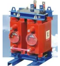
The single-phase grounding transformer is primarily used in generators with neutral points and in the neutral grounding resistance cabinets of Satons transformers, aiming to reduce the cost and size of the resistance cabinet.
■ Job characteristics
(1) The zero-sequence impedance is low to ensure the output of zero-sequence current;
(2) High excitation impedance to reduce no-load current;
(3) Low no-load loss to save energy consumption during daily operation.
■ Wiring method
YNyn connection
Transformers with this connection mode generally adopt a three-phase, three-column core. The neutral point on the high-voltage side can be connected to an arc suppression coil or other devices to achieve grounding. However, when the zero-sequence current of single-phase grounding flows through the high-voltage side winding, the generated zero-sequence magnetomotive force cannot be balanced by the secondary magnetomotive force, and the zero-sequence magnetic flux in the same direction cannot form a loop within the three-column core. As a result, a large amount of zero-sequence magnetic flux can only form a closed loop through the clamps, oil, and the body of the oil tank, causing additional losses in the oil tank and clamps, leading to local overheating and limiting the utilization of transformer capacity. The relevant operating procedures of China's power sector have made the following provisions regarding the working state of the neutral point of YNyn connected transformers connected to an arc suppression coil:
(1) The capacity of the arc suppression coil shall not exceed 20% of the rated capacity of the transformer;
(2) The zero-sequence voltage drop generated within the transformer by the zero-sequence current flowing through the arc suppression coil shall not exceed 10% of the rated phase voltage;
(3) The total three-phase zero-sequence current flowing through the arc suppression coil shall not exceed 60% of the rated phase current of the transformer. The aforementioned regulation is primarily determined based on the condition that the local overheating caused by the zero-sequence magnetic flux does not exceed the ***maximum temperature*** of the transformer winding hot spot.
From the above, it can be seen that the capacity of the grounding transformer with YNyn connection is far from being utilized, and its zero-sequence reactance value is also relatively large.
YNd connection
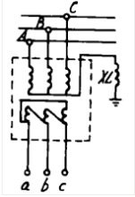
The characteristic of this connection method, where the YNd connection transformer is connected to the arc suppression coil XL, is that the delta connection on the secondary side provides a closed path for zero-sequence current, resulting in a smaller zero-sequence reactance. Additionally, since the zero-sequence magnetomotive force of the primary and secondary windings on each core limb is balanced, the zero-sequence leakage flux is also reduced. However, when the YN connection winding is externally positioned, the additional zero-sequence losses caused within components such as the oil tank cannot be completely avoided. When it is connected to the arc suppression coil, the utilization of its capacity will still be subject to certain limitations. Foreign experimental research has shown that, after considering factors such as additional losses, localized overheating, insulation life, and the maximum temperature of winding hot spots, the permissible operating mode for YNd-connected grounding transformers is as follows:
(1) When operating at twice the rated load, the capacity of the arc suppression coil connected to the YN side must not exceed 50% of the rated capacity of the transformer;
(2) When the secondary load is only 50% of the transformer capacity during normal times, the arc suppression coil capacity can be equal to the rated capacity of the transformer.
Although the secondary side of this connection can supply power to regional loads or for the substa tion's own use, its application is greatly limited due to the difficulty of supplying power to both power and lighting users simultaneously in a delta connection.
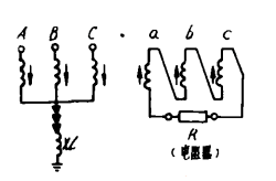
YN, open d connection is similar to YNd connection in that it is linked to the arc suppression coil XL. The open d connection method allows for the insertion of a resistor or reactor on the side of the open delta to adjust the zero-sequence reactance of the transformer. The insertion of a resistor can also suppress ferroresonance in the network. If a three-phase five-column core is used, the zero-sequence impedance value can be greatly increased, and it may even be possible to eliminate the need for an arc suppression coil. However, this structure is complex and increases the cost. Additionally, the secondary use of open delta wiring cannot meet the needs of supplying power to regional loads and self-consumption, so this method is not widely adopted.
ZNyn connection
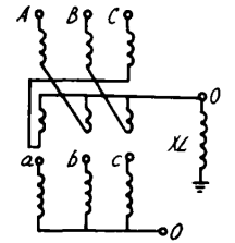
The connection method of linking a ZN, yn connected transformer with an arc suppression coil XL is a commonly used connection method for grounding transformers. Due to the fact that the zero-sequence magnetomotive forces in the upper and lower half windings on the same core limb of the zigzag connection method are exactly equal in magnitude and opposite in direction, they cancel each other out, resulting in minimal zero-sequence leakage flux. This in turn leads to a very small zero-sequence reactance value, and its capacity can be equal to that of the connected arc suppression coil.
The grounding transformer widely adopted both domestically and internationally primarily adopts this connection method. Due to the yn connection method employed on the low-voltage side, it can simultaneously supply power to regional electricity consumption or the substation's own electricity consumption. The capacity of the low-voltage side is often smaller than that of the high-voltage side, and in most cases, the capacity of the low-voltage side ranges from 80 to 200 kVA.
Although the rated capacity of the high-voltage side can be equal to the capacity of the connected arc suppression coil, the Z-connection method will require 1.15 times more turns than the Y-connection method. Therefore, the actual capacity of the grounding transformer should be 1.15 times the capacity of the arc suppression coil.
■ Operating principle
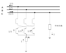
The working principle diagram of the grounding transformer during a single-phase fault in the system is illustrated using the commonly used ZNyn connection. During operation, when a certain magnitude of zero-sequence current passes through, the current directions of the two single-phase windings on the same core column are opposite and equal in magnitude, causing the magnetic potential generated by the zero-sequence current to exactly cancel each other out, thus resulting in a very small zero-sequence impedance.
This allows the neutral point of the grounding transformer to flow through a compensating current in case of a fault. Due to the very small zero-sequence impedance, when zero-sequence current passes through, the resulting impedance voltage drop should be as small as possible to ensure system safety. Since the grounding transformer has a low zero-sequence impedance, when a single-phase grounding fault occurs in phase C, the phase-to-ground current I of phase C flows into the neutral point through the earth and is equally divided into three parts flowing into the grounding transformer. Since the three-phase currents flowing into the grounding transformer are equal, the displacement of the neutral point N remains unchanged, and the three-phase line voltages remain symmetrical.
However, in the manufacturing process, the number of turns and geometric dimensions of the upper and lower windings of the high-voltage winding cannot be exactly equal, making it impossible for the magnetic potential generated by the zero-sequence current to exactly cancel each other out. Instead, a certain zero-sequence impedance is generated, usually around 6-10Ω. Compared to the zero-sequence impedance of 600Ω in star-connected transformers, its advantage is self-evident. In addition, the zigzag grounding transformer can also minimize the no-load current and no-load loss. Compared to ordinary star-connected transformers, since each phase core of the zigzag-connected transformer consists of windings from two core limbs, as can be seen from its vector diagram, when the voltage is the same, it requires 1.16 times more windings. In the neutral-point resistance grounding mode, the amplitude difference between zero-sequence impedance and positive-sequence impedance is significant in urban distribution networks during single-phase grounding. When three-phase positive and negative-sequence currents flow through, the magnetic potential on each core limb of the grounding transformer is the phasor sum of the magnetic potentials of two windings belonging to different phases on that core limb. The magnetic potentials on the three core limbs form a set of three-phase balanced quantities with a phase difference of 120°, generating magnetic flux that can form loops on the three core limbs. This results in a small magnetic circuit resistance, large magnetic flux, and high induced electromotive force, exhibiting significant positive and negative-sequence impedances. Therefore, the grounding transformer has the characteristics of large positive and negative-sequence impedances and small zero-sequence impedance.
■ Main technical parameters
To meet the needs of arc suppression coil grounding compensation in distribution networks and to satisfy the power and lighting load requirements of substations, it is necessary to select transformers with Z-type connections and set the main parameters of the grounding transformers appropriately.
(1) The primary side capacity of the grounding transformer with rated capacity should be matched with the capacity of the arc suppression coil. Based on the existing capacity specifications of the arc suppression coil, it is recommended to set the capacity of the grounding transformer to be 1.05-1.15 times that of the arc suppression coil. For example, if a 200kVA arc suppression coil is used, the capacity of the grounding transformer should be 215kVA.
(2) Total current flowing through the neutral point of the transformer during a single-phase fault with neutral compensation current:
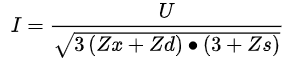
In the above formula:
U represents the line voltage of the distribution network (V); Zx denotes the impedance of the arc suppression coil (Ω);
Zd represents the primary zero-sequence impedance (Ω/phase) of the grounding transformer;
Zs represents the system impedance (Ω);
The duration of the neutral point compensation current should be the same as the continuous operating time of the arc suppression coil, which is specified as 2 hours.
(3) Zero-sequence impedance: Zero-sequence impedance is an important parameter of grounding transformers, which has a significant impact on relay protection, single-phase grounding short-circuit current, and overvoltage suppression. For grounding transformers with a zigzag (Z-type) connection without secondary coils and star/open delta connections, there is only one impedance, namely the zero-sequence impedance. This allows the manufacturing department to meet the requirements of the power sector.
(4) Losses: Losses are an important performance parameter of grounding transformers. For grounding transformers with secondary windings, their no-load losses can be made comparable to those of double-winding transformers of the same capacity. For load losses, when the secondary side is operating at full load, due to the lighter load on the primary side, the load losses are less than those of a double-winding transformer of the same capacity on the secondary side.
(5) According to the national standard, the temperature rise of grounding transformers is specified as follows:
1) The temperature rise under rated continuous current should comply with the provisions of the general national standard for dry-type transformers, but it is mainly applicable to grounding transformers that often carry load on the secondary side;
2) When the duration of short-term load current is within 10 seconds (this situation mainly occurs when the neutral point is connected to a resistor), its temperature rise should comply with the temperature rise limit provisions under short-circuit conditions specified in the national standard for power transformers;
When the grounding transformer operates together with the arc suppression coil, its temperature rise should comply with the regulations for the temperature rise of the arc suppression coil: for windings that continuously flow through the rated current, the temperature is 80K, which is mainly applicable to grounding transformers with star/open delta connections; for windings with a maximum rated current flow time of 2 hours, the specified temperature is 100K.
This situation aligns with the operating conditions of most grounding transformers; for windings with a maximum circulation time specified as 30 minutes, the specified temperature is 120K. The starting point for the aforementioned specifications is based on the premise that under the most severe conditions, the maximum temperature of the winding hot spot does not exceed 140℃~160℃, in order to ensure the safe operation of insulation and prevent it from seriously compromising the insulation life.